Sheet.Developments

Screenshots

What it actually looks like

Five shots from the current build — not mock-ups, not a designer's impression. Every number in them came out of the software. Click any image to see it full size.

The way in

Pick a shape and start

Twenty-four shapes, grouped the way a shop thinks about them rather than alphabetically. Quick Design is one part straight to a DXF with no job around it; New Job adds the parts list, materials and costing when you need to quote.
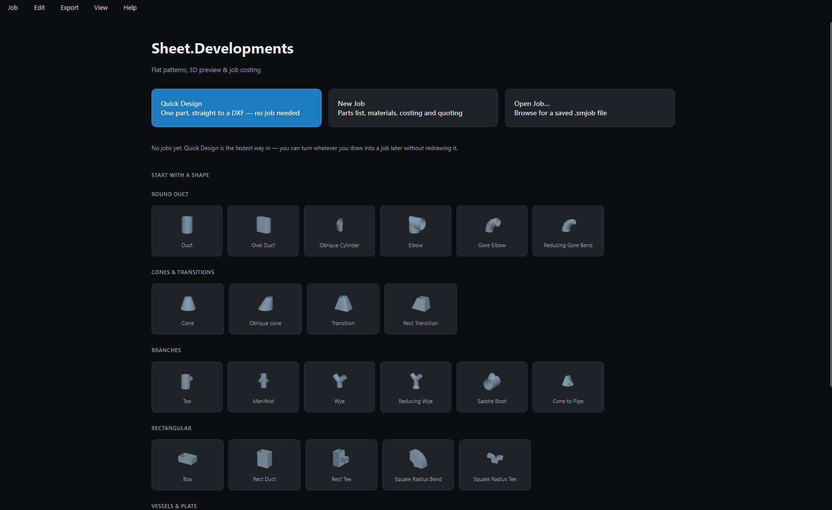
The Sheet.Developments start screen, showing Quick Design, New Job and Open Job, with the shape library below grouped into Round Duct, Cones and Transitions, Branches and Rectangular

Anything you draw in Quick Design can be turned into a job later without redrawing it.
The development

A cone, with the wall thickness already in it

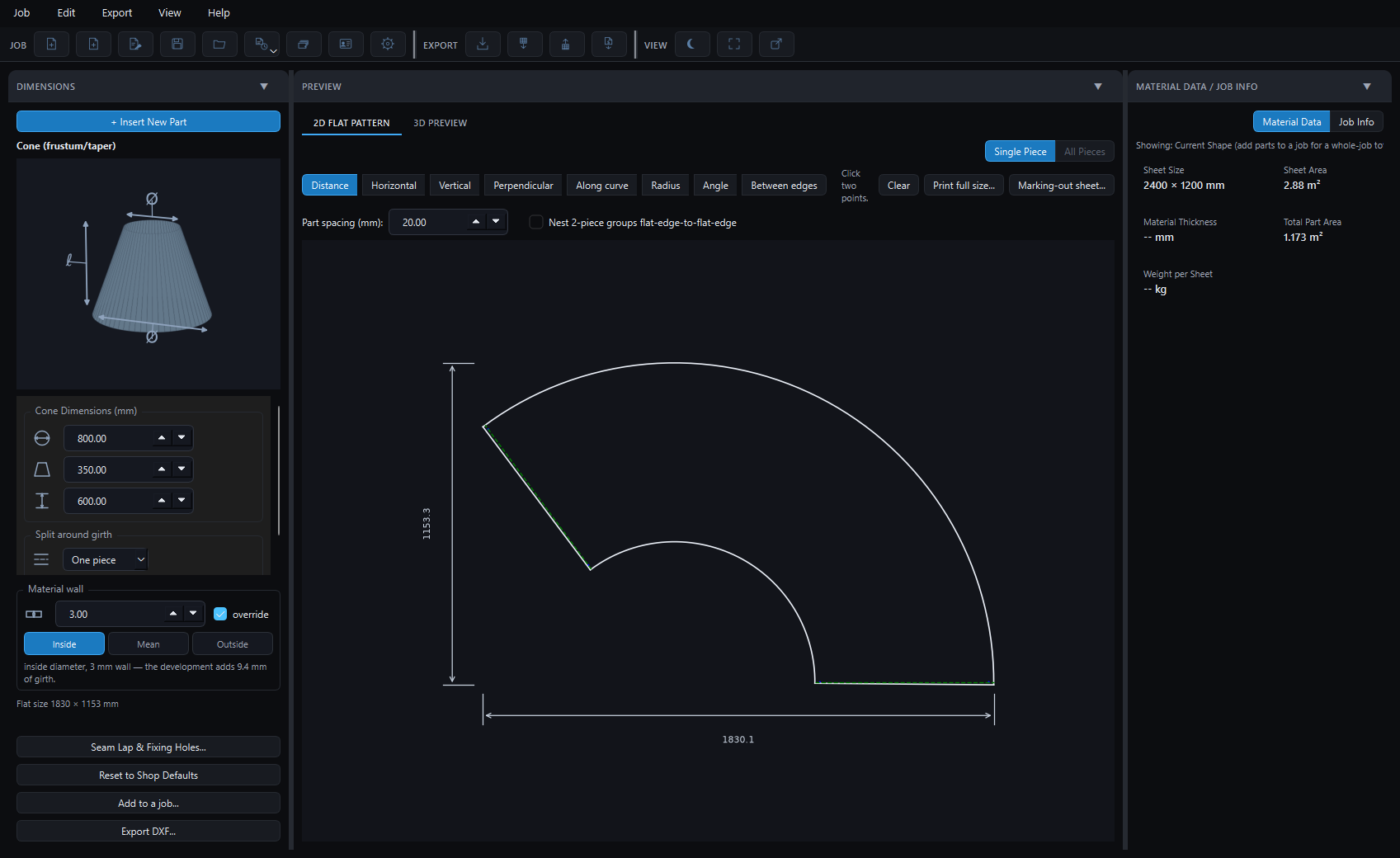
An 800 to 350 cone, 600 high, in 3 mm plate. The diameters were typed as inside diameters, so the pattern develops on the middle of the material and the girth comes out 9.4 mm longer than the bare numbers would give. Seam laps are drawn in green, on their own DXF layer.

A cone development on screen: dimensions panel on the left showing 800, 350 and 600 with a 3 mm wall on an inside-diameter basis, the flat pattern in the middle with its overall size dimensioned
Flat size 1830 × 1153 mm Girth added by the wall 9.4 mm Warns before it won't fit the sheet

Before you cut

See the part, not just the blank

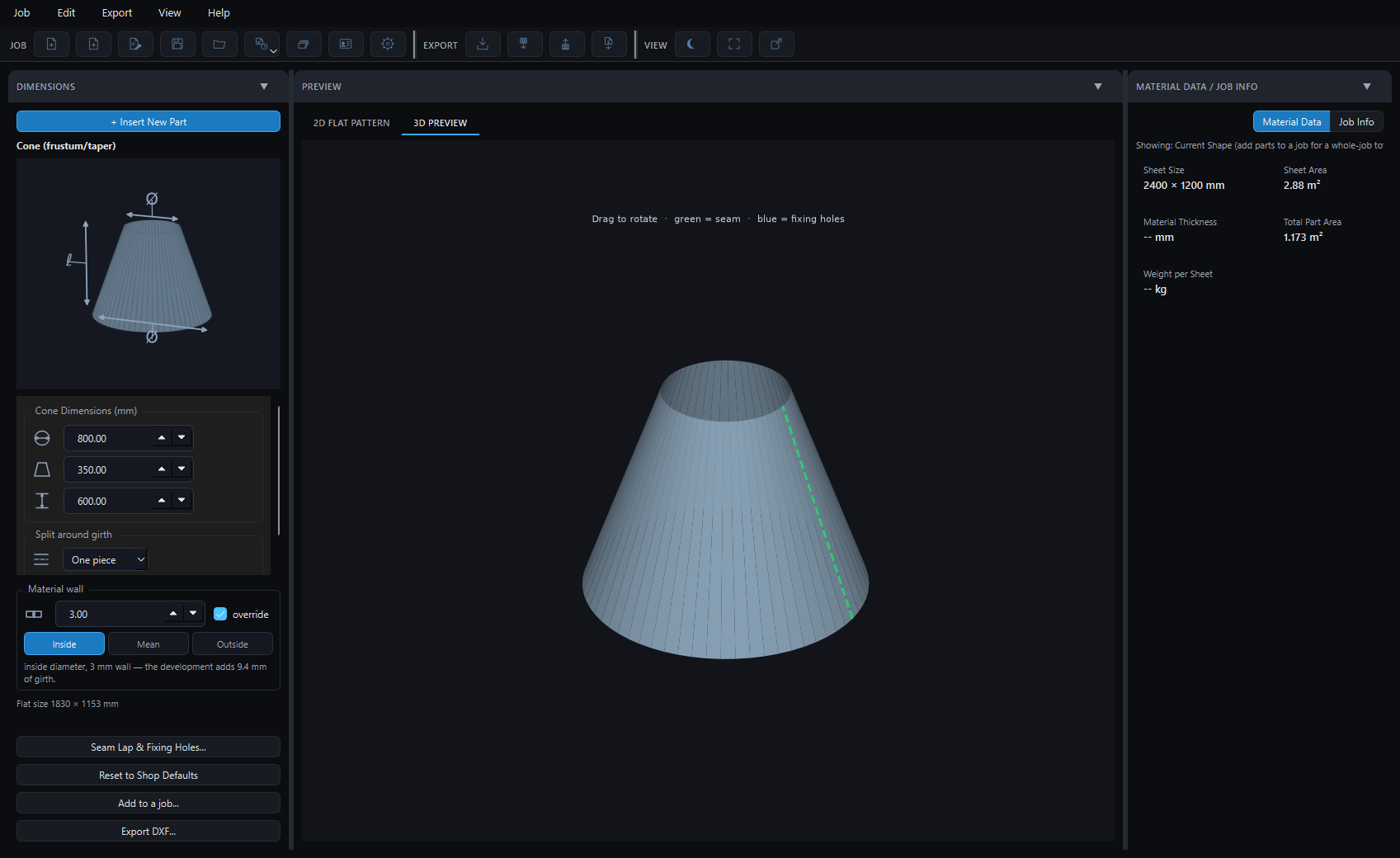
The same cone rolled up. Drag to turn it. The seam is green and any fixing holes are blue, so you can see where the joint lands before the plate is on the machine — which is the cheapest time to notice it is in the wrong place.

The 3D preview tab showing the cone shaded and rolled up, with the seam marked as a green dashed line down its side

Checking

Measure anything on the pattern

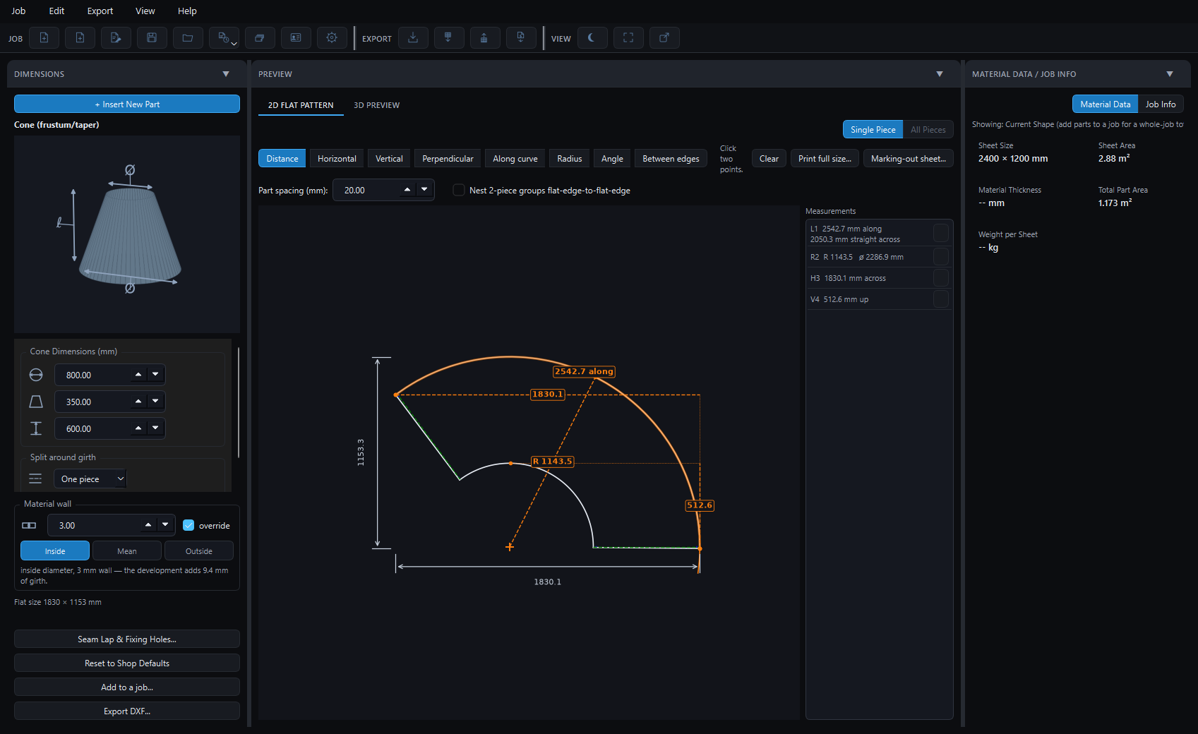
Eight kinds of measurement, and the picks snap to ends, centres, midpoints, quadrants and intersections. Along curve runs the tape around the arc rather than straight across it — between the same two points on this cone that is the difference between 2050 mm and 2543 mm. Every measurement stays on the drawing and comes out on the marking-out sheet.

The flat pattern with four measurements marked on it in orange: a length along the outer arc, a radius, a horizontal size across the blank and a vertical size, with the values listed in a panel beside the drawing
Along the arc 2542.7 mm Straight across the same two points 2050.3 mm Radius R 1143.5

The detail most software gets lazy about

Inside, mean or outside — say which

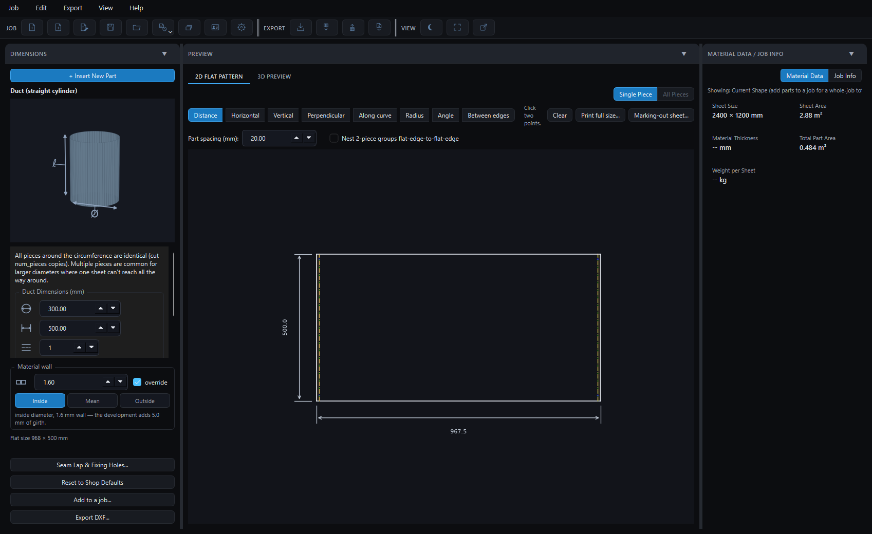
A 300 duct in 1.6 mm. If 300 is the inside diameter, the blank is not π×300. It is π×301.6, because the material rolls about its middle — 5 mm of girth, which is a 5 mm gap or a 5 mm overlap at the seam. Set it per part; the software says in plain words what it did.

A straight duct pattern with the Material wall panel showing a 1.6 mm wall on an inside-diameter basis and the note: inside diameter, 1.6 mm wall, the development adds 5.0 mm of girth
Typed 300 inside Develops on 301.6 Blank 968 × 500 mm

What is not in these shots

Sheet nesting and NC output exist but are not merged yet, so they are not pictured — I would rather show you what is finished. If cutting is your end of the job and you would like to try that part early, there is a tester list.

30-day trial

Try it on a part you already know the answer to.

That is the only test worth doing. Develop something you have cut before, check the girth against your own numbers, and see whether it agrees.

Get early access Try the free cone calculator