Flat pattern development
Sheet.Developments unrolls the parts a plate shop actually makes — cones, hoppers, lobster-backs, tank heads, branches into cones — and gives you a DXF, a full-size template and a price. Windows desktop, works offline, no subscription to your own drawings.
In private beta. 30-day trial when it ships.
The job
Triangulation on the shop floor works — it has for a century — but it is slow, it does not scale to a job with forty fittings, and every transcription is a chance to be out by a few millimetres. General CAD will draw you the solid and then leave you to work out the development yourself.
This does the development. Type the sizes off the drawing, watch the 3D preview to check you have described the right part, and take the flat pattern away as a DXF, a marking-out sheet or a full-size paper template.
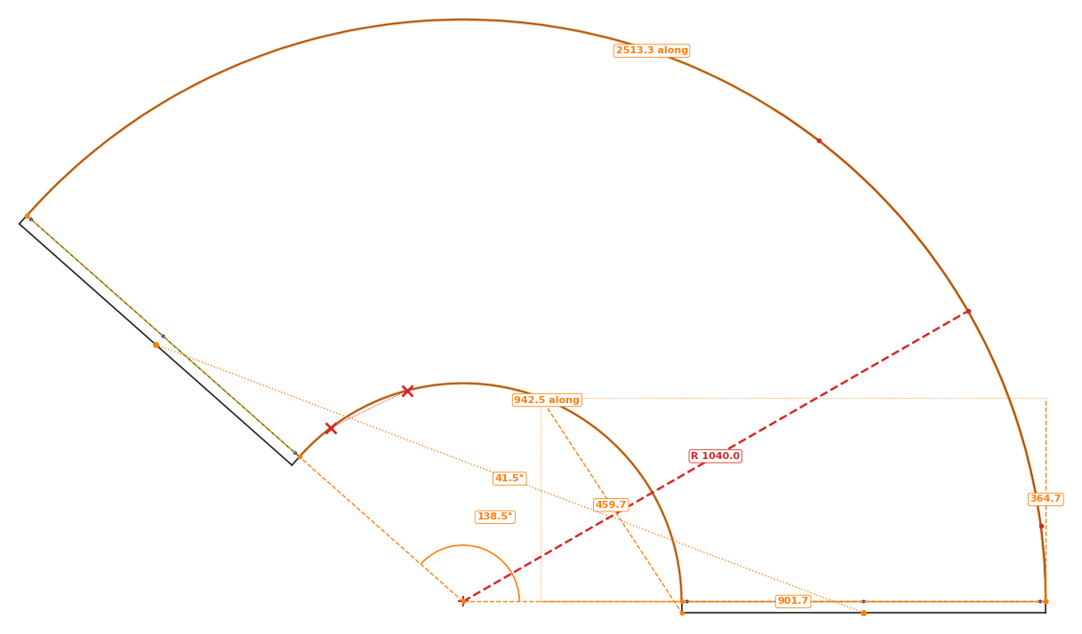
A cone development with its end girths, radius and throat measured on screen. Measuring along a curve follows the metal, so it reads the rolled circumference — not the straight line across it.
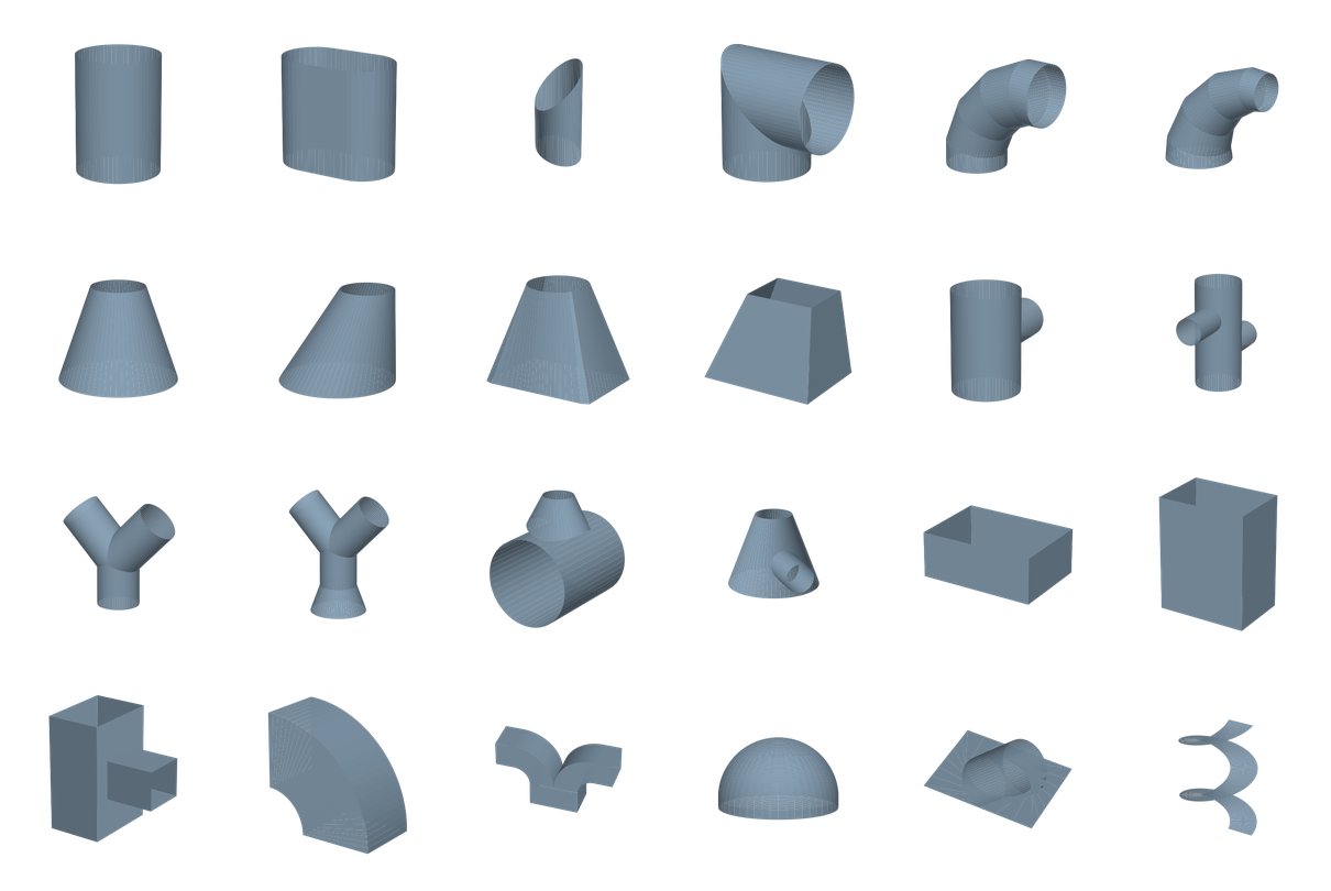
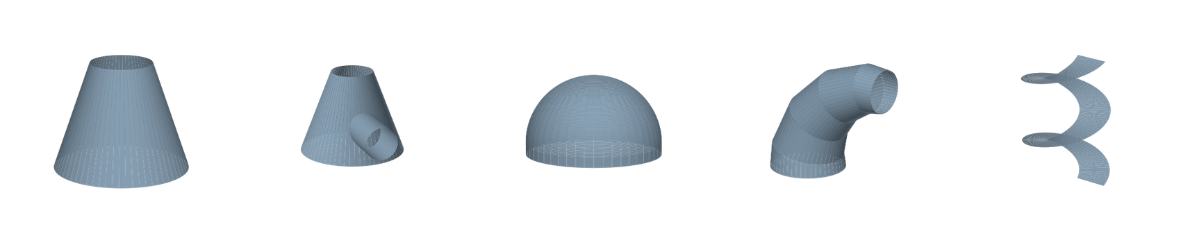
The library
Every one developed properly — true lengths, neutral-axis girths, seam laps and end allowances on all four edges, and a girth split when the part is bigger than your plate.
Why it fits
Rolled metal stretches on the outside and compresses on the inside. The length that does neither runs up the middle of the material, so that is what the pattern has to be developed on. Most software assumes the number you typed was already that mean diameter. No drawing says mean diameter — it says 300 NB, or 300 ID, or 300 OD.
Tell it which, and it does the rest:
| Part | Inside | Mean | Outside | Spread |
|---|---|---|---|---|
| 300 dia × 1.2 mm | 946.2 | 942.5 | 938.7 | 7.5 mm |
| 600 dia × 3 mm | 1894.4 | 1885.0 | 1875.5 | 18.8 mm |
| 900 dia × 6 mm | 2846.3 | 2827.4 | 2808.6 | 37.7 mm |
Girth in millimetres. On thin duct a lap swallows the difference. On 6 mm plate it is a scrapped cylinder.

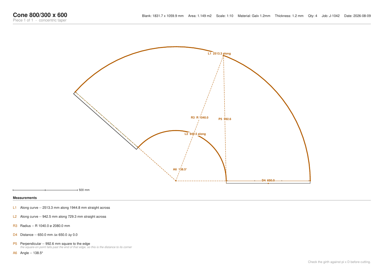
The marking-out sheet. Drawn at a real, stated scale from the drawing-office run — never "shrunk to fit" — with a scale bar that survives a photocopier.
In the shop

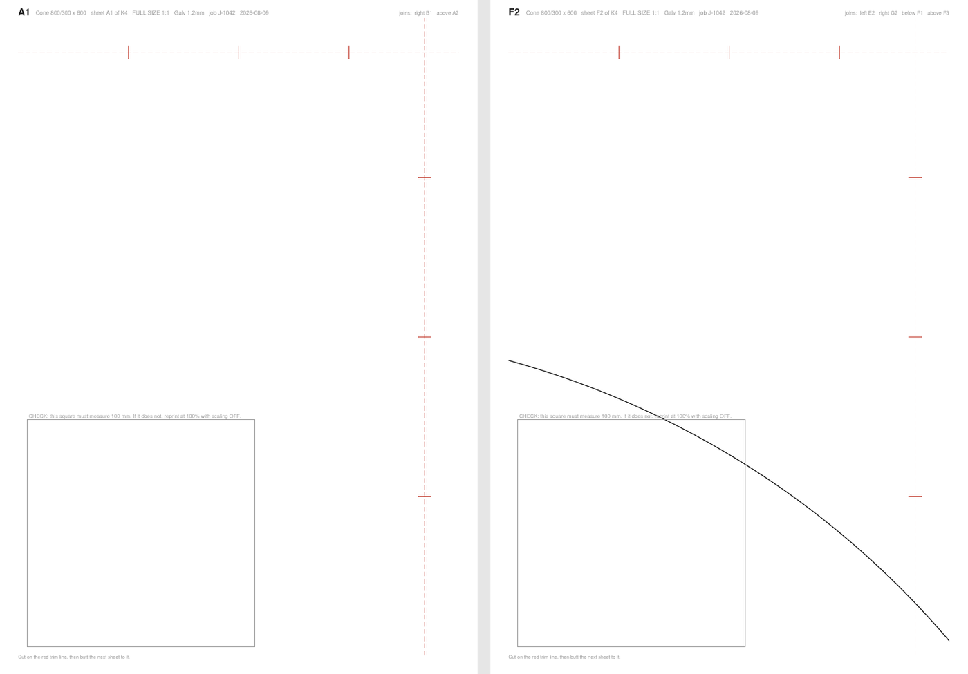
Full size across as many sheets as it takes. Tiles overlap and carry a trim line, so the join is exact whatever your printer's margins are — and every sheet has a 100 mm check square, because "fit to page" is on by default in half the drivers out there.
Layers you control, arcs or polylines, mm or inches, your own part stamp. Bend, seam, guide and allowance lines each on their own layer, so nothing gets cut that shouldn't be.
Import a take-off CSV in whatever layout your shop already uses, price the job against your own materials and rates, and produce a quote PDF on your letterhead.
Type 3-1/2, 3 1/2 or 3.5 — all three work, and it reads back in fractions to the nearest 1/16. Everything is stored in millimetres underneath, so a job crosses between shops without changing size.
There is a nesting engine and a post-processor in here that take a job, lay the parts onto your stock and offcuts, add kerf compensation and lead-ins, and write the program for your table. It is not finished and it is not in the build yet, because getting a cutting program subtly wrong is a much more expensive mistake than getting a drawing wrong.
If you run a plasma or laser table and would put it through a real job on a machine you can afford to babysit, I would like to hear from you — that feedback is the only thing standing between it and shipping.
Pricing
A licence is tied to the machine it is activated on and works without an internet connection. Your jobs are plain files on your own disk; nothing is held hostage if you stop paying, because there is nothing to stop paying.
Early-access users get the launch price locked in.
Early access
It is in private beta now. Leave an email and I will send you a build to put through a job of your own — and I would rather hear what is wrong with it than what is right.
One email when the beta build is ready, and one when it ships. Nothing else, and no passing your address to anyone.